Geometries of Radiometry Technical Note
| Geometry | Typical Units | Question it Answers | Typical Applications |
| Total Radiant Flux | W (Watts) | How much total power does the source emit in all directions? | Lamps, bulbs, discrete LEDs, and source-to-source production comparisons |
| Irradiance | W/m2 | How much power reaches a surface at a specific distance? | Solar, grow lighting, UV exposure, solar simulators, environmental and process measurements |
| Radiance | W/m2/sr | How much power comes from a viewed area in a defined direction? | Displays, illuminated indicators, extended glowing surfaces, imaging and night-vision work |
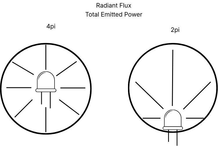
Total Radiant Flux
Total radiant flux is the total radiant power emitted by a point source in all directions, integrated over a range of wavelengths. The SI unit is watt (W). For a lamp or LED that emits in many directions, the source is typically placed inside the integrating sphere so that all the light leaving the source can be collected, regardless of the direction.
Choose total radiant flux when the central question is how much total optical power the entire source produces in all directions. Because the sphere captures the directional output, this geometry is especially useful for repeatable source-to-source comparisons and production quality control by removing directionality as a variable.
Typical applications include:
- Comparing lamps, bulbs, or LEDs during development and manufacturing
- Verifying total optical output after changes in drive current, thermal management, materials, or assembly
- Characterizing sources whose emission is distributed over a wide or irregular angular pattern
Set-Up considerations: The integrating sphere, source mounting position, baffles, ports, electrical leads, and any fixture inside the sphere can affect the measurement. The calibrated configuration should be reproduced as closely as possible. It is recommended to get an IS-Lamp for self-calibration for multiple source types and samples.
Irradiance
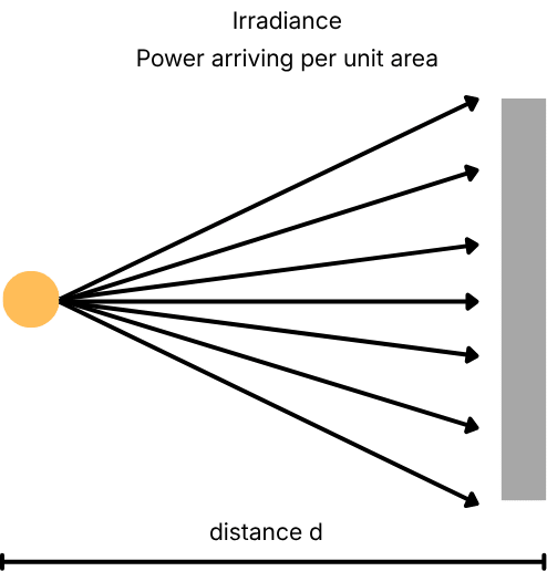
Irradiance is radiant flux incident on a surface per unit area. Its SI unit is W/m². An irradiance measurement is made at a defined location at a specific distance and orientation with a cosine-corrected receptor.
This popular geometry is often the most practical choice when performance depends on the dose or power density received by a target or surface. Unlike total radiant flux, irradiance changes with distance, alignment, beam shape, and obstructions. Those variables should be documented and held constant for comparisons.
Typical Applications include:
- Horticultural and grow lighting — quantify spectral irradiance at canopy level and calculate photon-based metrics such as PPFD over the appropriate wavelength range.
- Solar and photovoltaic research — measure solar spectral irradiance or verify the irradiance delivered by a solar simulator to a test plane.
- UV exposure and curing — determine the incident UV power density and, when combined with exposure time, calculate radiant exposure or dose.
- Photochemistry — some chemical processes require UV light to drive them, such as photochromic inks and dyes, irradiance can be used to calculate the exposure or dose
- Industrial, architectural, and roadway lighting — evaluate the optical radiation reaching a work plane, roadway, product, or other target at the intended distance.
- Automotive and transportation lighting — characterize the radiation delivered toward a roadway or test target under controlled geometry.
- Environmental monitoring — measure sunlight, artificial sky glow, or other radiation incident at a monitoring location.
Radiance
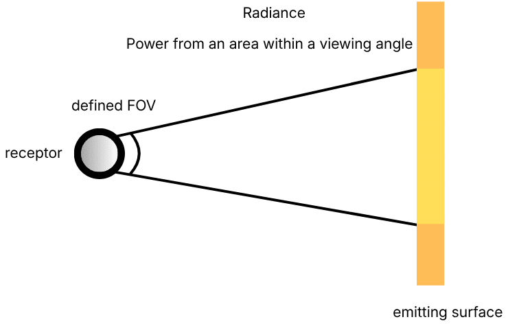
Radiance describes radiant flux leaving, passing through, or arriving at a projected area within a defined solid angle and direction. Its SI unit is W/(m²·sr). A radiance configuration uses an imaging optic or defined field of view so the system measures the light from a selected area of the source rather than all emitted light or all light incident on a surface.
Radiance is the preferred geometry for extended sources such as displays, screens, illuminated buttons, instrument panels, diffuse emitters, and night-vision-compatible lighting. It answers a directional viewing question: how much radiation is coming from this apparent area toward the receptor?
Typical applications
- Displays and screens — measure the spectral radiance, luminance, color, and uniformity of LCD, OLED, microLED, mobile-device screens, computer monitors, and other displays at a defined location and viewing angle.
- Night-vision-compatible lighting — verify the radiance and spectral output of cockpit instruments, vehicle displays, control panels, and indicators operating at very low light levels.
- Illuminated controls and indicators — characterize backlit buttons, instrument panels, status indicators, and other emitting surfaces as they appear to an observer or imaging system.
- Imaging and sensor calibration — characterize integrating-sphere ports, uniform radiance sources, and reference targets used to evaluate cameras, detectors, satellite imaging, inspection cameras, traffic cameras, and other optical imaging systems
- Luminous panels and diffuse emitters — evaluate light boxes, illuminated signage, diffusers, exit signs, and other extended sources where the emitting area and viewing direction are important.
Defining the Measurement
The calibration geometry should represent the final measurement configuration. Before selecting a calibration, document:
- Source type and physical size: point-like, extended, diffuse, collimated, or directional
- What is the job the DUT is designed for?
- Wavelength range of interest
- Expected power level and dynamic range
- Working distance, orientation, field of view, and illuminated or viewed area
- Whether the output should be radiometric, photon-based, photometric, colorimetric, or a combination
- Required traceability, uncertainty, repeatability, and environmental conditions
With this information, one of StellarNet’s Application Scientists can configure a system to suit your needs.
StellarNet’s spectroradiometer systems can be configured for total radiant flux, irradiance, or radiance measurements across UV, visible, and near-infrared wavelength ranges.
Typical Radiometer Systems and Configurations
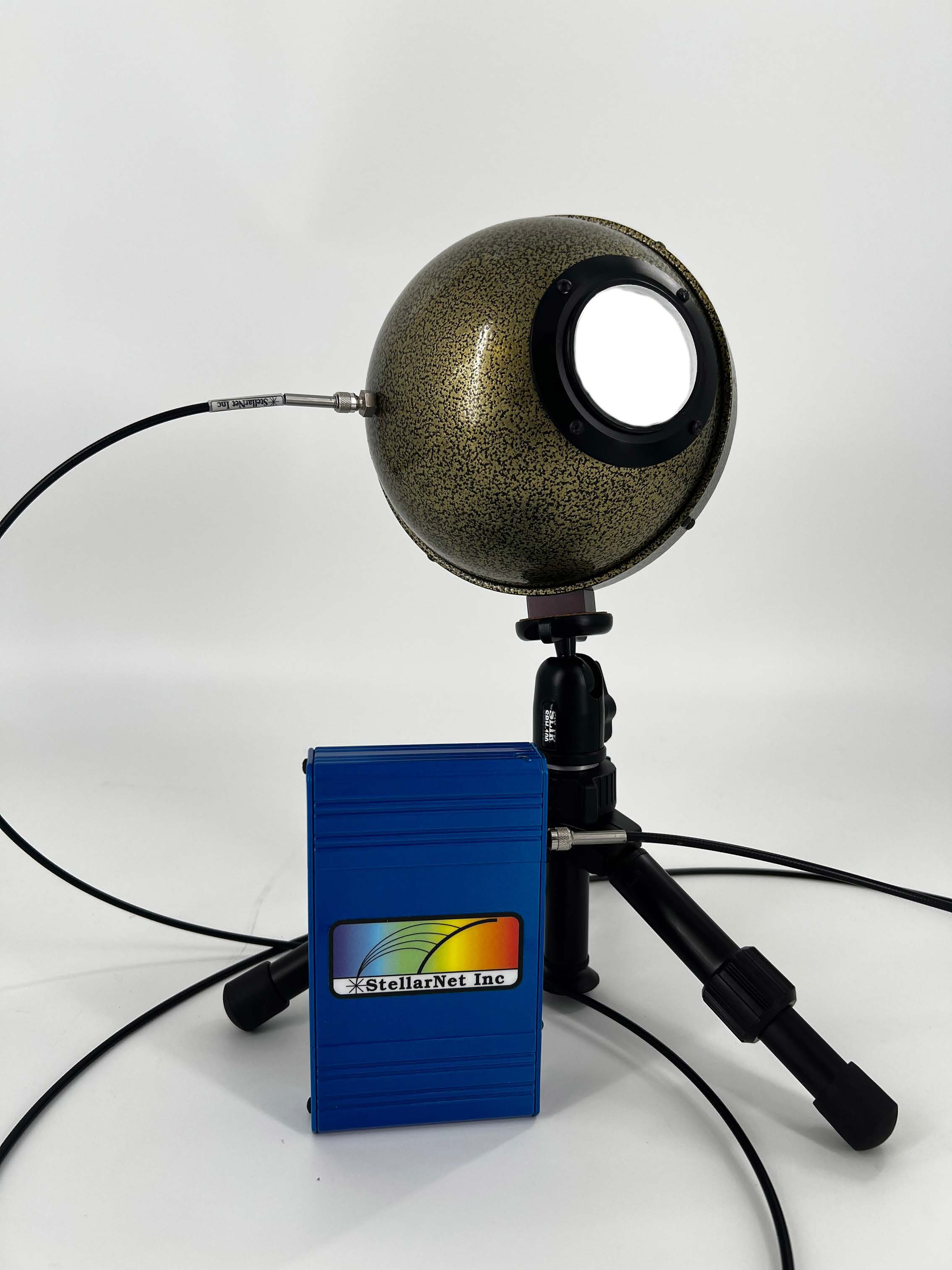
Radiant Flux Measurements: BLUE-Wave + Fiber + Sphere
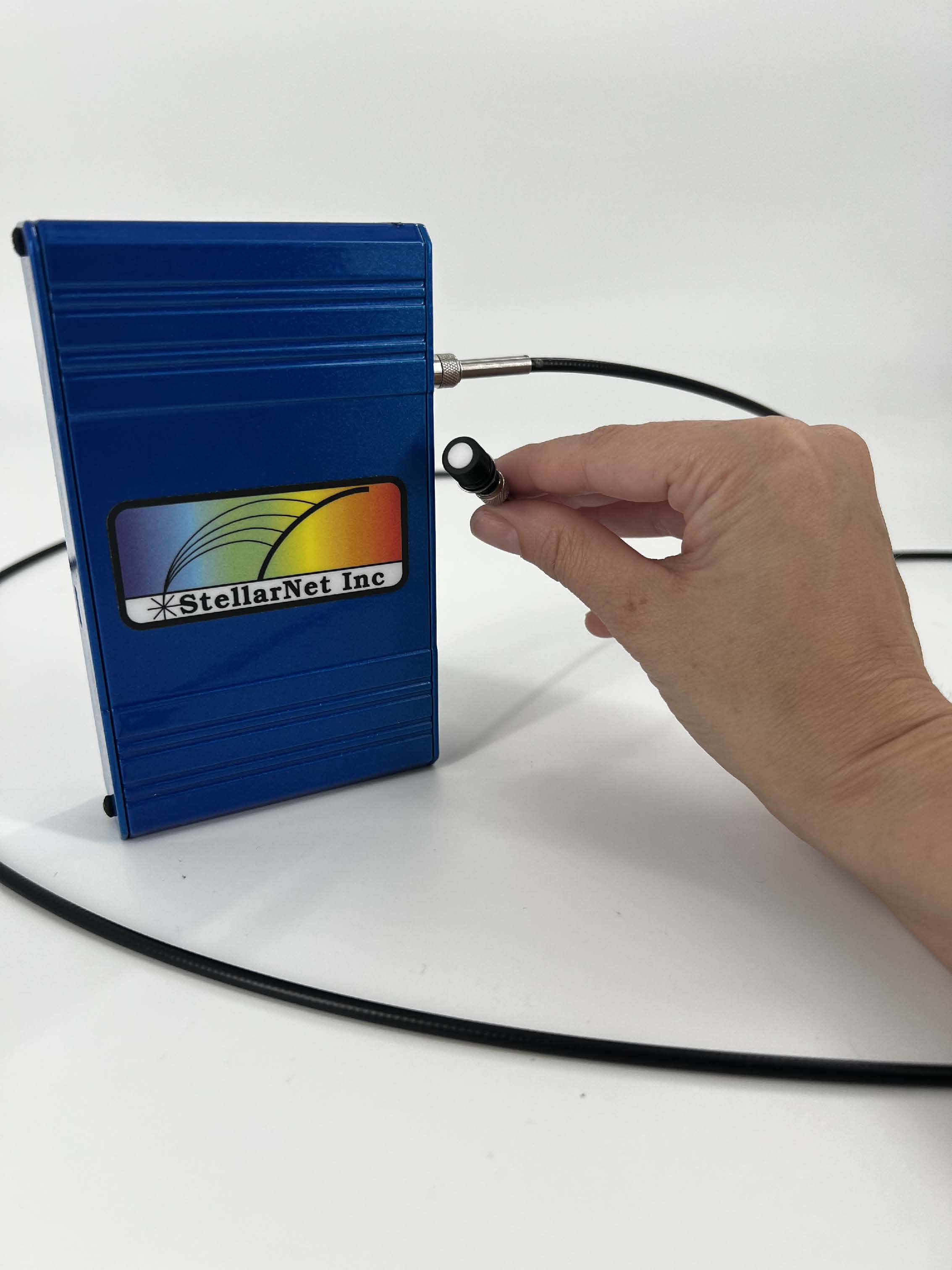
Irradiance Measurements: BLUE-Wave + Fiber +Cosine Receptor
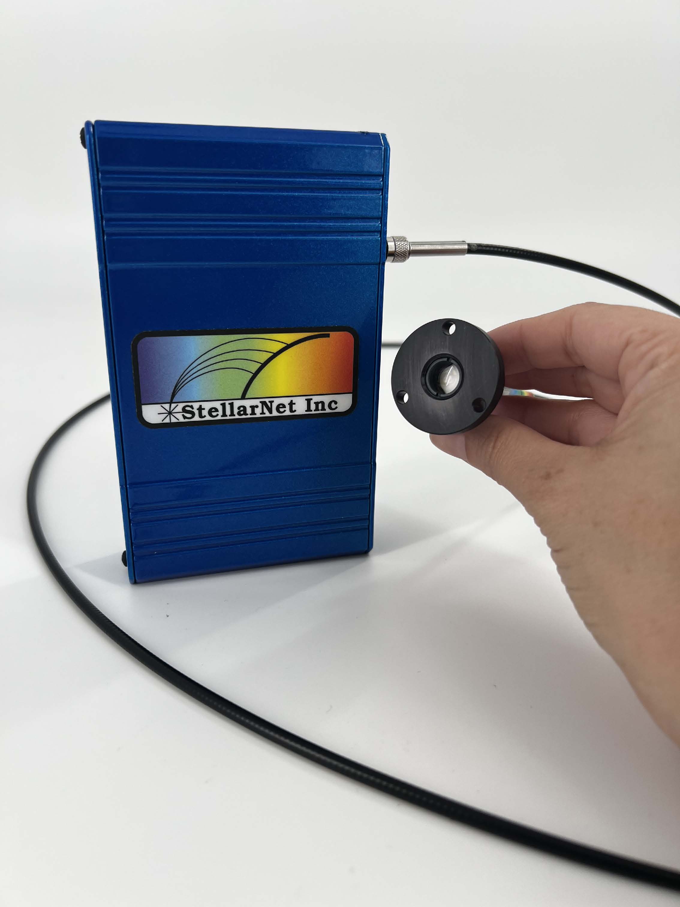
Radiance Measurements: BLUE-Wave + Fiber + Cosine Receptor + Lens Assembly
Technical references
National Institute of Standards and Technology (NIST), “Radiometry and Photometry: Review for Vision Optics.” https://www.nist.gov/publications/radiometry-and-photometry-review-vision-optics
U. Datla and A. C. Parr, “Introduction to Optical Radiometry,” NIST. https://tsapps.nist.gov/publication/get_pdf.cfm?pub_id=104704
L. Wyatt, Symbols, Terms, Units and Uncertainty Analysis for Radiometric Sensor Calibration, NIST Handbook 152. https://nvlpubs.nist.gov/nistpubs/Legacy/hb/nisthandbook152.pdf